Key takeaways
16 min read
Key point 1
The critical point isn't the flue, but the junction between the flue and a light, thin, ribbed roof, where water runs channelled along the valleys of the profile.
Key point 2
Good practice for a pitched roof at a penetration is to divert the water to the sides at the top and to provide protection covering a band at least 20 cm high above the roof.
Key point 3
Flue outlet height is set by the regulations for your project; as a reference, more than 1 m above the roof or ridge, with additional criteria above 20° pitch or with nearby obstacles.
Key point 4
Sandwich panel brings two conditions that don't exist with single-skin sheet: continuity of the insulation and the vapour barrier, and distance to combustible materials when the core is combustible.
Key point 5
The piece that crowns the outlet must fit the real diameter of the flue. VENTUM® caps are made to measure with a manufacturing allowance of 3 mm per side.
In this article
- What Changes When the Roof Is Sheet Metal or Sandwich Panel
- The Three Pieces Involved: Penetration, Flashing and Top Cap
- What Good Practice Asks for Where an Element Passes Through the Roof
- How High the Mouth of the Flue Should Be
- Where to Place the Penetration: the Criterion That Avoids Half the Problems
- How Watertightness Is Achieved on Ribbed Sheet
- Sandwich Panel Adds Two Layers: Insulation and Vapour Barrier
- Distance to Combustible Materials: the Point Most Often Overlooked
- The Top Cap: Protecting the Mouth and Stabilising the Draught
- Why the Piece Is Made to Measure and What Data Is Needed
- Common Mistakes on Lightweight Roofs
- VENTUM® Caps by Industrias Mas
- Frequently asked questions
Profiled metal sheet and sandwich panel roofs dominate industrial units, agricultural sheds, prefabricated housing and a good share of extensions to existing buildings today. They are quick to erect, light and economical. And they have one particular point that is very often badly resolved: the passage of a chimney flue or a ventilation duct through them.
On a tiled roof over a concrete or masonry deck, that junction is resolved with building work: there is mass to build into, to bed and to finish. On a metal sheet roof there is none of that. There is a sheet less than a millimetre thick, with ribs that channel the water, resting on purlins, expanding and contracting in the sun and, in the case of sandwich panel, also being the building's insulation and its vapour barrier. Any badly resolved hole becomes a leak, and a leak in a unit rarely falls where it doesn't matter.
This guide explains how that junction is resolved: where the penetration should go, how watertightness is achieved on a ribbed profile, what changes when the roof is sandwich panel and what role the top cap plays in protecting the mouth and in how the draught behaves.
Section 02
What Changes When the Roof Is Sheet Metal or Sandwich Panel
Five characteristics distinguish a lightweight roof from a traditional one, and all five directly affect the flue cap.
Thickness. The sheet is tenths of a millimetre thick. There is no material to build a piece into or to bed it in mortar. The whole system works by mechanical fixing and lapping, not by adhesion or weight.
Ribbing. Water doesn't run over a continuous plane. It runs channelled by the valleys between the ribs. Any piece that cuts across several ribs interrupts those channels and creates a dam upstream, exactly where you don't want one.
Low pitch. Profiled metal roofs are laid to much lower pitches than tile roofs, with the minimum depending on the profile and the manufacturer's guidance. At those pitches water moves slowly and any obstacle makes it pool.
Thermal movement. A metal roof exposed to the sun heats up a lot and cools quickly. That daily cycle produces expansion and contraction that the roof absorbs at its supports and laps. If the flue is rigidly tied to the sheet, that movement ends up unpicking the sealing or fatiguing the fixing.
The multiple function of the envelope. With a single skin, the roof is a cladding and little more. With sandwich panel it is cladding, thermal insulation and, through its inner sheet, a vapour barrier. Perforating it affects all three functions at once.
Section 03
The Three Pieces Involved: Penetration, Flashing and Top Cap
When someone asks for a cap for the chimney flue they are usually thinking of a single piece. In reality three are involved, and it's worth telling them apart because each solves a different problem.
- The penetration. The hole made in the roof and the element that resolves it around its perimeter and edge. In sandwich panel it includes treatment of the cut edge of the core and sealing on the inner face.
- The weathering flashing. The piece that sits on the roof around the flue and carries the water to the sides and downwards. On site it's known as an apron flashing.
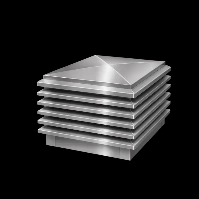
- The top cap. The piece that crowns the mouth of the flue: the chimney cap or terminal. It protects the outlet from direct rain, stops the wind pressing on the mouth and keeps the free passage area.
Leaks are concentrated almost always in the first two. Draught and downdraught problems, in the third. A well-resolved project addresses all three.
Section 04
What Good Practice Asks for Where an Element Passes Through the Roof
Good detailing practice for pitched roofs, and manufacturers' installation guidance, converge on a handful of conditions where a pipe or duct passes through the roof. The figures below are those used in Spain's CTE, and we give them here as a design reference rather than as a citation of a UK clause; check the requirements that apply to your project.
For pitched roofs, which covers practically all metal sheet and sandwich panel roofs, three conditions apply. First, penetrations shouldn't be placed in valleys. Second, the upper part of the junction between the flashing and the penetrating element must be resolved so that the water is diverted to the sides of it. Third, around the perimeter of the junction there must be protective elements, prefabricated or formed on site, that cover a band of the penetrating element above the roof at least 20 cm high.
For flat roofs, there is an additional condition on position: penetrations should be kept at least 50 cm away from junctions with vertical walls and from elements projecting above the roof, and the protective elements should rise at least 20 cm up the penetrating element above the roof protection.
There is a fourth requirement that is often forgotten and that is very relevant on lightweight roofs: anchor points shouldn't be placed in valleys and should be protected by elements covering a band at least 20 cm high above the roof. Since a flue of any height almost always needs bracing, its anchors are also water-passage points and must be treated as such.
Translated to site: the penetration isn't put where it suits the installation, but where the roof allows it; the piece that resolves it has a minimum height above the roof; and the water arriving from above must be divided towards the sides before reaching the flue.
Section 05
How High the Mouth of the Flue Should Be
With watertightness resolved, there is the other half of the problem: where the flue ends. Outlet height and its distance from the ridge, from openings and from nearby buildings are governed by the regulations in force for your project (in England, Approved Document J covers combustion appliances and flue outlets), so check the rules that apply to you and, in case of doubt, leave it to a qualified installer.
As an order of magnitude, the Spanish standard UNE 123001 on modular chimneys is a common reference: the chimney cap should sit more than 1 m above the roof or the ridge. Where the roof pitch is above 20°, it's enough to meet one of two conditions: the cap more than 1 m above the ridge, or a horizontal distance from the cap to the roof surface greater than 2.5 m. Against nearby obstacles, the criterion is to clear them in height or to place the chimney at a horizontal distance greater than twice the height of the obstacle.
On an industrial unit these criteria look easy to meet, because the roof is large and clear. It's worth looking twice: rooflights, static extractors, air-conditioning units, neighbouring ducts and taller adjacent buildings are obstacles for all practical purposes, and a large-surface unit generates wind flows over the roof that punish outlets that are badly sized in height.
Section 06
Where to Place the Penetration: the Criterion That Avoids Half the Problems
The position of the penetration conditions everything else. These are the design criteria that work best on lightweight roofs:
- Never in the valley. It's the worst possible place: the valley concentrates the water of two slopes.
- As close to the ridge as possible. The higher the penetration, the less roof surface pours water onto it, the less length of flue is exposed to wind and the less height has to be gained to clear the ridge.
- Respecting the profile geometry. A penetration that interrupts one whole, clean valley, with the piece resting on the adjacent crests, is preferable to one that cuts half a rib and leaves the flashing biting into the edge of the rib.
- Away from transverse laps. Laps between sheets are already delicate points. Adding a penetration a few centimetres from them multiplies the risk.
- Separated from other elements. The 50 cm criterion mentioned above for flat roofs is a reasonable reference here too: rooflights, anchors, lifelines, downpipes and equipment deserve distance.
- Compatible with the structure. The penetration must fall between purlins, not on one of them, and the flue must be supportable from the structure and not from the sheet.
This last point deserves emphasis. The sheet is not a load-bearing element for the flue. The weight of the chimney, its thrust under wind and maintenance loads are transmitted to the structure through their own supports. If the flue rests on the roof, it deforms it, and a deformed sheet stops carrying the water where it should.
Section 07
How Watertightness Is Achieved on Ribbed Sheet
The aim is simple to state: the water running down the roof must go round the flue without touching the hole and carry on its way. These are the principles that make it possible.
- Divert the water at the top. The upper part of the junction receives all the run-off from upstream. It must be resolved with a piece that divides it towards the sides before it reaches the flue. On site this is done by extending the flashing under the upstream sheet or by fitting a pointed apron that acts as a divider.
- Always lap in the direction of the water. The piece goes under the sheet upstream and over the sheet downstream. Reversing that order at a single point turns the whole assembly into a funnel.
- Rest on the crests, don't obstruct the valleys. The base of the flashing must conform to the pitch and height of the rib, or be raised on a plinth above the waterline. A flat flashing screwed onto a ribbed profile leaves gaps underneath by definition.
- Fix on the crest and seal continuously. Fixings go on the high part of the profile, with screws and sealing washers, never in the bottom of the valley, where the water flows. Sealant is applied in a continuous bead on a clean surface, not in spots.
- Cover at least 20 cm of flue. The vertical band mentioned above isn't an aesthetic detail: it's what stops splashing or wind-driven water entering at the joint.
- Allow for movement. Between the piece and the flue there must be a joint able to absorb differential expansion. A rigid seal between two metals that move differently has an expiry date.
- Watch compatibility between metals. Avoid direct contact between aluminum and copper, and pay attention to metal pairs in damp or salt-laden environments, fitting separator gaskets where necessary.
And a warning that saves many aftercare visits: sealant is a complement, never the solution. A penetration resolved with mastic alone lasts a winter. The geometry of the pieces and the laps are what last twenty.
Section 08
Sandwich Panel Adds Two Layers: Insulation and Vapour Barrier
A sandwich panel consists of two metal sheets and an insulating core bonded to both, and is manufactured and classified to the European standard EN 14509. The inner sheet isn't just a finish: in practice it acts as the vapour barrier of the envelope. Perforating it to pass a flue interrupts three continuities at once.
Continuity of the insulation. The hole creates a local thermal bridge. In an environment where the indoor air is warm and humid — a unit with a process, a home with a stove — that cold spot is a candidate for condensation.
Continuity of the vapour barrier. If sealing is done only on the outside, indoor water vapour finds a direct path into the panel. The result isn't a visible leak, but moisture accumulating at the edge of the core and corrosion from within. Sealing on the inner face is as important as on the outside.
Integrity of the edge. The cut leaves the core exposed all round the perimeter. That edge must be protected and sealed: it's the way moisture gets into the panel.
In addition, the penetration piece has to be designed for the real thickness of the panel. An apron flashing designed for single-skin sheet doesn't cover the edge of a 40, 60 or 100 mm panel, and the junction is left incomplete. Where a condensation risk calculation predicts condensation, a vapour barrier is needed under the thermal insulation; perforating the envelope without restoring that barrier cancels that provision locally.
Section 09
Distance to Combustible Materials: the Point Most Often Overlooked
The most common sandwich panel cores are polyurethane or polyisocyanurate foams, expanded polystyrene and mineral wool. The first three are organic materials; mineral wool is not. The difference matters a great deal when what passes through the panel is a duct carrying combustion gases at high temperature.
Modular metal chimneys are designated to the EN 1856 series of standards, and that designation includes, among other parameters, the minimum distance to combustible materials declared by the duct manufacturer. That distance isn't indicative: it's an installation condition. When the duct passes through a building element containing combustible material, it has to be guaranteed, usually by a sleeve or through-piece that maintains the separation and, depending on the system, allows that space to be ventilated.
Two practical consequences follow. The first is that a single-wall flue isn't the right solution for passing through a roof with a combustible core. The second is that the hole must be sized on that declared distance, not on the diameter of the flue. It's a frequent mistake: the panel is cut to the exact size of the duct and sealed, leaving the organic insulation in direct contact with the outer wall of the flue.
The reaction to fire of the panels and the conditions for passing services through them are part of the project and fall under the fire-safety regulations that apply to the building, not an assembly detail.
Section 10
The Top Cap: Protecting the Mouth and Stabilising the Draught
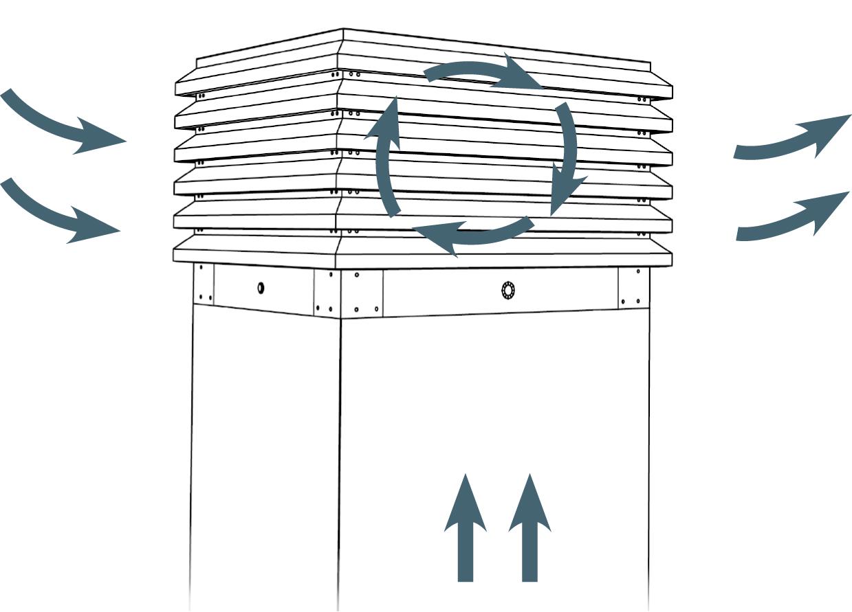
With the penetration resolved, there is the piece that crowns the outlet. Its function is threefold: to stop direct rain entering the mouth, to stop the wind pressing on it and causing downdraught, and to keep the free passage area the gases need to leave without being choked.
On unit roofs, that function counts for more than on a terraced house. A large, clear roof, often on an industrial estate or in open country, leaves the flue exposed to strong, unsteady wind, with changes of direction and gusts that translate into draught fluctuations. The geometry of the cap is what makes that exposure manageable.
There are two families of solution. The static cap works with no electrical consumption, relying on its own geometry and on the action of the wind on the mouth. It covers most installations. The mechanical cap incorporates forced extraction and is reserved for cases where natural draught isn't consistently sufficient or where the process demands a stable airflow. We cover it in detail in this article on mechanical vs static chimney caps, and how draught works is explained in what a chimney cap is and how it works.
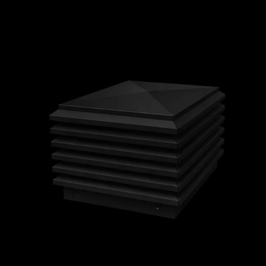
As for material, the choice is between lacquered aluminum and stainless steel. On a lightweight roof the weight of the piece isn't usually decisive, but two factors are: the aggressiveness of the environment — proximity to the sea, industrial atmospheres, the process's own effluents — and colour, because lacquering the cap in the same RAL as the roof makes the piece stop reading as an add-on. The full criteria are in the guide to choosing between stainless steel and lacquered aluminum.
When the outlet is for ventilation and not for smoke, the approach is the same, with ventilation terminals in place of chimney caps.
Section 11
Why the Piece Is Made to Measure and What Data Is Needed
A standard cap answers to a catalogue of diameters. A real flue answers to a specific manufacturer, system and wall thickness, and the roof it rests on answers to a commercial profile with its own rib pitch. The probability that both coincide with a catalogue piece is low, and when they don't, improvised shims, sheets bent on site and gaps that let water in appear.
That's why VENTUM® caps are made to the size of each outlet, with a manufacturing allowance of 3 mm per side. This is the information that lets the piece be defined without ambiguity:
- Real outside diameter of the flue, measured on the installed piece, not the nominal diameter of the inner duct.
- Type of flue: single wall or insulated twin wall, and the commercial system if known.
- Roof profile: type of sheet or panel, rib pitch and height, and total thickness in the case of sandwich panel.
- Roof pitch and orientation of the penetration relative to the line of steepest slope.
- Clear height available above the mouth and distance to the ridge and nearby obstacles.
- Use: smoke extraction or ventilation, and the fuel or process involved.
- Environment: inside an industrial estate, rural setting, proximity to the sea or an atmosphere with chemical load.
- Finish: RAL colour wanted, or stainless steel.
With that information, the piece is made to fit. Without it, it's made to approximate, which is something else.
Section 12
Common Mistakes on Lightweight Roofs
- Placing the penetration in the valley or a few centimetres from a transverse lap. They are the two worst possible locations.
- Relying on sealant for watertightness. Mastic follows the geometry; it doesn't replace it.
- Reversing the lap. Placing the piece over the sheet upstream guarantees a leak, even if everything else is well executed.
- Fixing in the valley of the profile. Every screw in the bottom of a valley is a perforation in the channel the water runs along.
- Resting the flue on the roof. The sheet isn't structure; the deformation it causes ends in a leak.
- Forgetting interior sealing on sandwich panel. The damage isn't seen until the core is wet and the inner sheet corroded.
- Cutting the hole to the exact size of the flue without respecting the distance to combustible materials declared for the duct.
- Leaving the mouth below the ridge or a nearby obstacle and expecting the cap to make up for the height error.
- Choosing the cap from a catalogue without measuring the real outside diameter of the outlet.
Section 13
VENTUM® Caps by Industrias Mas
VENTUM® is the range of chimney caps and ventilation terminals from Industrias Mas Salvadó y Sucesores, S.L.U., a manufacturer of aluminum construction products since 1968 and an ISO 9001:2015 certified company. The range is available in static and mechanical versions, in lacquered aluminum in any RAL colour or in stainless steel, and is made to the size of each outlet with a manufacturing allowance of 3 mm per side.
On metal sheet and sandwich panel roofs, that made-to-measure manufacture is what lets the cap fit the real diameter of the flue and the finish of the roof, instead of forcing the installation to adapt to a catalogue piece. If you have a penetration to resolve, tell us the case: flue diameter, type of roof and intended use are usually enough to point to the solution.
FAQ
Frequently asked questions
Why does water leak in through metal sheet roofs?+
Almost always at the junction between the flue and the ribbed sheet. The three most common reasons are a reversed lap, a flat piece resting on a ribbed profile that leaves gaps underneath, and the absence of an element that diverts to the sides the water arriving from the top.
Does a standard cap work?+
It depends on the real outside diameter of the flue matching a catalogue size and on the junction with the roof being resolved separately. When they don't match, a made-to-measure piece avoids improvised shims and gaps.
Does sandwich panel change anything compared with single-skin sheet?+
The watertightness principle is the same, but two conditions are added: continuity of the insulation and the vapour barrier, which means sealing on the inner face too and protecting the cut edge, and the distance to combustible materials when the core is an organic foam.
How high should the mouth of the flue be?+
It's governed by the regulations that apply to your project. As a reference, the Spanish standard UNE 123001 puts the cap more than 1 m above the roof or the ridge. With pitches above 20° the alternative of placing the cap more than 2.5 m horizontally from the roof surface is also accepted. Against obstacles, you clear them in height or move away more than twice their height.
Can I pass through a panel with a polyurethane core?+
Yes, as long as the distance to combustible materials declared for the duct in its designation is respected, normally with a through-piece that maintains that separation. What isn't acceptable is cutting the hole to the exact size of the flue and leaving the core in contact with the wall of the duct.
Can the penetration be resolved with sealant alone?+
It's not a lasting solution. Sealant supports the geometry of the pieces and the laps, but on its own it can't withstand the thermal movement of a metal roof or the concentrated run-off of a ribbed profile.
Do you make this type of cap to measure?+
Yes. VENTUM® caps are made to the real diameter of the outlet and the characteristics of the installation, in lacquered aluminum or stainless steel, with a manufacturing allowance of 3 mm per side.
Related product
VENTUM®
Made-to-Measure Chimney Caps and Cowls
Made-to-measure chimney cap, static and mechanical
Share
Sources
- CTE. Documento Básico HS Salubridad (Ministerio de Vivienda y Agenda Urbana) — apartados 2.4.3.1 (tabla 2.10, pendientes de cubiertas inclinadas), 2.4.4.1.6, 2.4.4.2.6 y 2.4.4.2.8.
- Documentos CTE. Salubridad (Código Técnico de la Edificación)
- IDAE. Guía técnica de instalaciones de calefacción individual — criterios de altura de chimeneas según la UNE 123001.