Key takeaways
16 min read
Key point 1
The top of a wall is an exposed horizontal surface: if water stays there, it gets into the wall and comes out on both faces as stains, efflorescence and spalling.
Key point 2
UK practice specifies coping to BS 5642-2 with NHBC detailing; commonly used design values are a slope of at least 10º and drip edges set at least 2 cm from the wall faces.
Key point 3
The starting figure for the order is the width of the wall top in millimetres; ALU-CLICK® is made to measure from 70 mm up to 600 mm wide.
Key point 4
The second figure is the linear metres of wall, and the third, the count of corners, T-junctions and ends.
Key point 5
The system has six pieces: profile, fixing strip, mitre, T piece, end cap and coupling.
Key point 6
The planned gap between pieces is 4 mm in summer and 8 mm in winter: it isn't slack, it's the expansion joint of the aluminum.
Key point 7
The system is installed with no silicone and no visible fixings, on a 70 mm strip with watertight bituminous joints.
In this article
- What a Wall Coping Is and What Problem It Solves
- Wall Coping, Capping and Wall Cap: the Same Element with Three Names
- What UK Practice Expects at the Top of a Wall
- Step 1: Measure the Width of the Wall Top, and Measure It Several Times
- Step 2: Measure the Length and Count the Runs
- Step 3: Define the Slope and the Direction of the Water
- Step 4: Resolve Corners, Junctions and Ends
- Step 5: Expansion, Where Durability Is Decided
- How the ALU-CLICK® System Works and Why It Has No Silicone
- Material and Finish
- Common Mistakes When Measuring and Ordering
- The Data Sheet to Send to the Factory
- ALU-CLICK® Wall Copings by Industrias Mas
- Frequently asked questions
The top of a wall is an exposed horizontal surface: if water stays there, it gets into the wall and comes out on both faces as stains, efflorescence and spalling.
UK practice specifies wall and parapet coping to BS 5642-2, with a slope and drip edges that keep water off the faces below.
The starting figure for the order is the width of the wall top in millimetres; ALU-CLICK® is made to measure from 70 mm up to 600 mm wide.
The second figure is the linear metres of wall, and the third, the count of corners, T-junctions and ends.
The system has six pieces: profile, fixing strip, mitre, T piece, end cap and coupling.
The planned gap between pieces is 4 mm in summer and 8 mm in winter: it isn't slack, it's the expansion joint of the aluminum.
The system is installed with no silicone and no visible fixings, on a 70 mm strip with watertight bituminous joints.
Section 02
What a Wall Coping Is and What Problem It Solves
A wall coping is the cap that crowns a wall, a low wall or a parapet on its upper face. Its function is to take rainwater off there and not let it penetrate the masonry.
Put another way: the top of a wall is the only practically horizontal plane of the whole element, and it's the point where water gets in most easily. Once inside, the wall behaves like a sponge. The water migrates downwards and sideways, and shows up as three very recognisable kinds of damage. Dark stains and streaks on both faces, because the water carries salts and dirt out from inside the masonry. Whitish efflorescence, when those salts crystallise as they dry on the surface. And spalling from freeze-thaw cycles, which on exposed walls ends up bursting the top course and the finish.
None of those three kinds of damage is fixed by cleaning. They're fixed by stopping the water getting in, and that is exactly what a properly sized wall coping does: it turns the top of the wall into a continuous, waterproof plane with a defined fall and with an edge that forces the drop to detach before touching the wall.
That's why, just as with window sills, the quality of the result depends less on the material than on the measurements. A wall coping with little overhang, no drip or poorly allowed for expansion protects little even if it's aluminum.
Section 03
Wall Coping, Capping and Wall Cap: the Same Element with Three Names
On site they are used interchangeably and it's worth being clear to avoid confusion when requesting a quotation or reading a specification.
Coping is the standard term. It's the one used in BS 5642-2 and in NHBC Standards when they cover the top of walls and parapets. If you're reading a construction specification or a schedule, this is the name you'll find.
Wall coping in the metal trade is also the commercial term most used in the aluminum and metal construction sector. It's what manufacturers, distributors and installers use.
Wall cap, capping or wall top are colloquial site variants that mean the same thing.
Historically, coping was made of stone, precast concrete or ceramic, and for that reason standards talk about pieces and joints between pieces. The metal wall coping solves the same problem with a different logic: instead of many pieces with many joints to seal, a continuous plane with controlled joints at specific points. That difference explains a good part of what follows.
Section 04
What UK Practice Expects at the Top of a Wall
Protecting the top of a wall against moisture is a core requirement of UK building design. Coping is specified to BS 5642-2, and detailing is guided by NHBC Standards (Chapter 6.11, Copings and Cills Detailing). Four conditions are commonly applied, and it's worth knowing them before measuring, because they directly condition what has to be ordered. The figures below are commonly used design values (they match those in Spain's CTE) rather than a citation of a specific clause; confirm the requirement for your project.
First: parapets and free-standing walls should be finished with a coping that carries away water reaching their upper surface and prevents it reaching the facade immediately below, or another solution that produces the same effect. That second route is important and we'll come back to it.
Second: coping should have a slope of at least 10º.
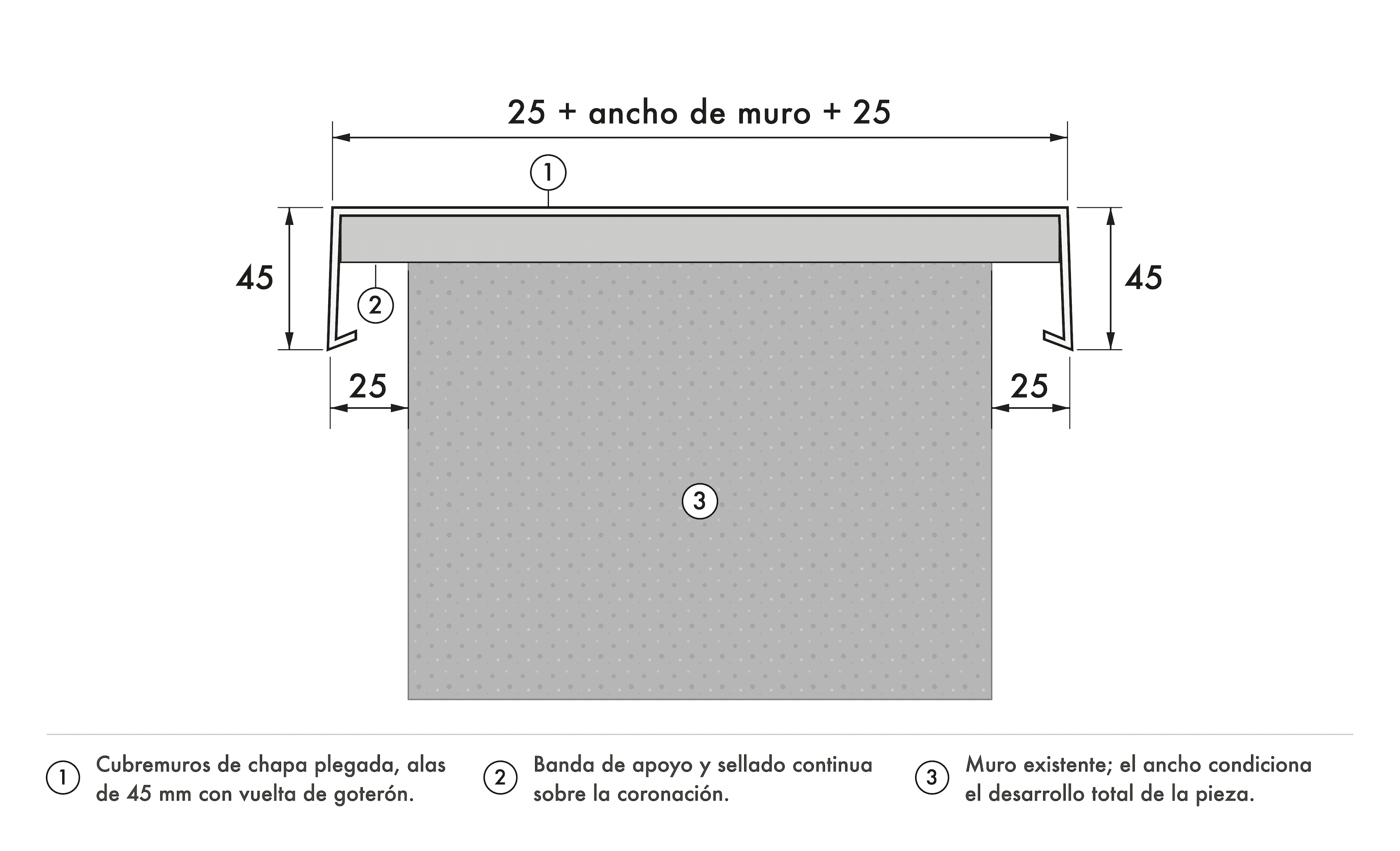
Third: it should have drip edges on the underside of the projections towards which the water runs, set at least 2 cm from the corresponding faces of the wall. If the water falls off both faces, drips are needed on both.
Fourth: it must be impermeable, or be laid on a waterproof barrier with that same minimum fall towards the outside.
To this is added a condition on joints that reveals the underlying problem: with stone, precast or ceramic coping, movement joints are needed at regular intervals, with the joints between pieces made watertight by suitable sealing.
That is the weak point of the traditional solution. A 20-metre wall finished with stone pieces has dozens of joints, and each one is a seal that ages, lifts and has to be maintained. The clause about 'another solution that produces the same effect' is precisely what allows the top of the wall to be resolved with a continuous metal cap: fewer joints, and those there are resolved by design rather than by mastic.
What doesn't change with the material is everything else. The fall outwards has to be guaranteed, the drips have to exist on both projections and the minimum separation from the wall face remains the same. That's why the profile's overhang on each side of the wall isn't an aesthetic detail: it's the dimension that determines whether the drip ends up where good practice requires.
Section 05
Step 1: Measure the Width of the Wall Top, and Measure It Several Times
It's the main figure of the order. It's measured from edge to edge of the top of the wall, on the finished surface and in millimetres.
Two warnings that save grief.
The first is that walls aren't regular. A rendered masonry wall can vary two or three centimetres along its length without being noticeable to the eye. It's worth measuring at several points — at least at the start, in the middle and at the end of each run, and always at the corners — and noting the maximum and the minimum values. If the difference is noticeable, say so on the order: it's information the factory needs to decide the girth.
The second is that the width of the wall top isn't the girth of the profile. The girth also includes the overhang on each side and the fold of the drip. The factory does that calculation from the width you send, and it's the reason the quotation form asks for the width of the wall and not the girth of the sheet: if you send the girth on your own, it's easy for the piece to end up with too little overhang.
As for limits, ALU-CLICK® is made to measure from 70 mm up to 600 mm wide. Most parapet and low walls fit comfortably in that range. If your wall exceeds 600 mm, it's a case to check before measuring any further.
A last note on the finish: if the wall is going to be clad, rendered or faced and isn't yet, measure to the design dimensions of the finished surface, not what's there today. It's the most frequent measuring mistake in new build.
Section 06
Step 2: Measure the Length and Count the Runs
The second figure is the linear metres of wall to be capped. They are measured along the centreline of the wall, following the real path, and noted by runs: the north face, the east face, the stair parapet, the terrace low wall.
Working by runs, and not with a single overall number, has three advantages. It lets you assign each run its own wall-top width, which can vary from one wall to another within the same job. It lets you count the junctions correctly, which is the next step. And it makes receiving the material on site easier, because the order arrives sorted by runs instead of as a heap of indistinguishable profiles.
On jobs with several widths it's also worth grouping: all the 300 mm runs together, all the 450 mm ones together. It reduces assembly errors and simplifies the cutting list.
Section 07
Step 3: Define the Slope and the Direction of the Water
This step decides where the water will fall for the next thirty years, so it deserves a minute's thought before ordering.
There are three linked decisions.
Where it should discharge. On a party wall or a roof parapet, it's almost always best to discharge towards the inside of the roof, where there is a collection system, and not towards the facade or the street. On a boundary wall with two exposed faces, a double-sided fall may suit to spread the water. On a wall against which a facade sits, the water has to be kept away from it.
What happens on the face that doesn't receive the fall. Even if the water discharges preferentially to one side, the other edge also gets wet: the wind pushes the rain and the run-off isn't perfectly symmetrical. That's why good practice calls for drips on the projections towards which the water runs, in the plural, and why it's worth the profile resolving the edge on both faces.
How the fall is achieved. A metal profile resting on a perfectly horizontal wall top will stay horizontal. If the wall doesn't already have a formed slope, it has to be resolved before fitting the cap. It's masonry work to be done beforehand, not something to improvise on assembly day.
In practice, the sensible thing is to state on the order the desired discharge direction per run and attach a sketch or a section when the wall has any particularity: a parapet that acts as the start of a balustrade, a stepped top, a junction with a pitched roof.
Section 08
Step 4: Resolve Corners, Junctions and Ends
A wall is rarely a straight line. And the points where it stops being one are exactly the points where water gets in if they aren't resolved with the right piece. The ALU-CLICK® system is made up of six elements, and it's worth knowing what each does in order to count them.
The profile is the cap proper, made to the width of the wall and cut into lengths.
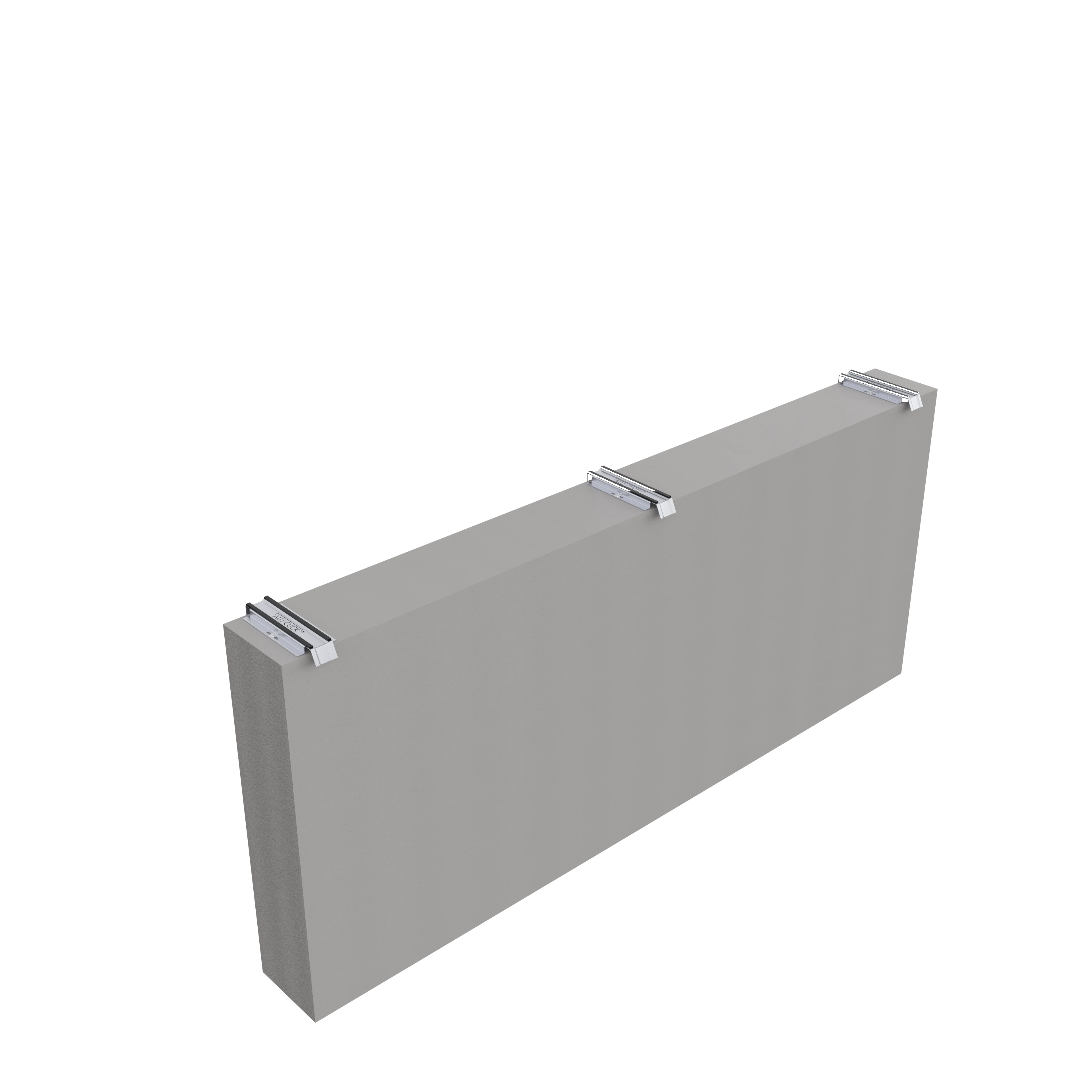
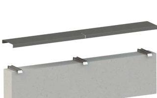
The fixing strip, 70 mm wide, is the base of the system: it's fixed to the wall and the profile clips onto it. It's the piece that means there are no visible screws.
The mitre resolves changes of direction: the corners of the wall, external or internal. It's counted by units, one per corner.
The T piece resolves junctions between walls, when one wall meets another at right angles and the continuity of the cap has to be maintained on all three arms.
The end cap closes the open ends of the profile. It's counted by units: a wall with two free ends takes two caps.
The coupling links consecutive lengths while maintaining the continuity of the cap and the watertightness of the joint.
Counting is simple if done on a plan sketch of the wall: you follow the layout marking corners, T-junctions and ends. That sketch, even hand-drawn, is worth more than any written description and is what's worth attaching to the order.
The website's quotation form is organised on exactly that logic: for each line you give the wall width in millimetres, the metres, the number of mitres and the number of end caps. If you have the sketch with the count done, filling it in takes a minute.
Section 09
Step 5: Expansion, Where Durability Is Decided
This is the part almost nobody takes into account when ordering and the one that causes the most problems in the medium term.
Aluminum expands with heat. A wall coping is a long element, dark in many cases, placed at the most exposed point of the building with nothing to shade it. In summer, the surface temperature of a RAL 7016 profile on a south-facing parapet can be well above the ambient temperature. And in winter, in the small hours, it can drop below zero.
If the profiles are fitted butt-jointed, with no gap, that movement has nowhere to go: the pieces push against each other, the cap buckles, the joints open where they shouldn't and the assembly loses the straight line that was half the reason for choosing it.
That's why the system provides for a gap between pieces of 4 mm in summer and 8 mm in winter. The difference isn't a whim: if you fit in August, the aluminum is already expanded and needs less gap; if you fit in January, it's contracted and you have to leave it room to grow. That gap isn't an assembly defect or a joint to be filled with silicone until it disappears: it's the system's expansion joint, and the coupling and the bituminous joint are what keep it watertight while it opens and closes through the year.
It's worth saying plainly because on site the temptation is the opposite: to press the pieces together so that 'the line doesn't show' and seal it. That is exactly what shouldn't be done.
Section 10
How the ALU-CLICK® System Works and Why It Has No Silicone
The system's approach is simple to explain. A 70 mm wide strip is fixed on the top of the wall. The wall coping profile snaps onto that strip, leaving the fixing hidden beneath the cap. Joint watertightness is resolved with bituminous joints.
From that come the three characteristics that define the system: zero silicone, zero visible fixings and fitting in one click.
The absence of silicone isn't an aesthetic matter. A silicone seal on the top of a wall works outdoors, in direct ultraviolet radiation, with daily expansion and with standing water on top. It's one of the seals that ages worst on a building, and its failure isn't seen until the stain appears on the facade, months later. A system that doesn't depend on it to be watertight eliminates that maintenance route at source.
The absence of visible fixings has the same basis. Every through-screw on an exposed horizontal plane is a perforation to be sealed and a potential corrosion point. If the fixing is hidden beneath the profile, those points don't exist.
And snap-fit installation reduces assembly time on site, which on a cap of tens of linear metres is no minor detail.
Section 11
Material and Finish
The profile is made in lacquered aluminum 1.2 mm thick, with 25 microns of polyester lacquer applied on both faces and high corrosion resistance.
Lacquering on both faces matters especially on this product. The hidden face of the wall coping is permanently in contact with the top of the wall, with the moisture it holds and with the masonry materials. It's the face that is never seen and the first to degrade on a cap protected only on top.
The finishes available are RAL 7016 anthracite grey, RAL 9006 natural, RAL 9003 white and RAL 7022 ash grey. Manufacture is under ISO 9001:2015 certification.
Compared with traditional solutions, aluminum brings three concrete things in this position: it doesn't rust, which rules out rust streaks on the facade; it weighs little, which simplifies assembly on high wall tops and on parapets that don't always take loads; and it allows long continuous pieces, so the number of joints is drastically reduced compared with a cap of short pieces.
Section 12
Common Mistakes When Measuring and Ordering
Measuring a single point on the wall. Walls vary. With a single measurement, the profile fits well at one end and is too big or too small at the other.
Sending the girth instead of the wall-top width. The factory calculates the girth from the wall width. Sending a girth you've already calculated, without saying so, is the quick route to a piece with no overhang.
Measuring on the unfinished wall. If the wall is going to be rendered or clad, the final width is greater. The piece will arrive tight and the drip will end up against the wall.
Not counting the corners. It's the first thing that's missing when the material arrives on site, and what forces improvised cuts that are neither watertight nor good-looking.
Fitting the pieces butt-jointed. Without the planned gap, the cap buckles in the first summer.
Sealing the expansion joint with silicone. It cancels the function of the joint and gives back to the system the problem it was designed to eliminate.
Not defining the discharge direction. If nobody decides, the chance of the wall top decides, and sometimes it decides to discharge towards the facade.
Leaving the colour to the end. Lacquering is applied at the factory; changing it afterwards means manufacturing again.
Section 13
The Data Sheet to Send to the Factory
With this, an order can be quoted without back-and-forth. For each run of wall:
- Width of the wall top in millimetres, stating the variation if the wall isn't regular.
- Linear metres of the run.
- Desired discharge direction.
- Number of mitres, stating whether external or internal corners.
- Number of T pieces.
- Number of end caps.
- RAL colour.
- Plan sketch of the wall, even hand-drawn, with the count marked.
- Planned assembly season, which conditions the gap between pieces.
The quotation form accepts attached documentation in PDF, JPG, PNG, XLSX, CSV, DWG and DXF up to 10 MB, so you can send the plan, the section or the construction detail directly. The response time for quotation requests is 24 hours on working days.
Section 14
ALU-CLICK® Wall Copings by Industrias Mas
The ALU-CLICK® wall copings are made to measure in lacquered aluminum, from 70 mm up to 600 mm wide, with a concealed fixing system on a strip, watertight bituminous joints and a full set of accessories — mitres, T pieces, end caps and couplings — to resolve the continuity of the cap along the whole run of the wall.
Industrias Mas Salvadó y Sucesores has manufactured aluminum construction products since 1968, with its own plant in Tàrrega (Lleida) and an ISO 9001:2015 certified quality system.
The system catalogue gathers the general characteristics and examples of completed work. To incorporate the system into the construction detail, the assembly drawing with dimensions and the 2D drawings of the strips are available: strip 1 and strip 2.
FAQ
Frequently asked questions
What measurement is essential for ordering a made-to-measure wall coping?+
The width of the wall top in millimetres. With it, the factory calculates the profile girth and the overhang on each side. The second figure is the linear metres, and the third, the count of corners, T-junctions and ends.
Up to what wall width is it made?+
ALU-CLICK® is made to measure from 70 mm up to 600 mm wide. Above that range, it's worth checking the case before closing the order.
What do standards say about capping a wall?+
In the UK, coping is specified to BS 5642-2, with detailing guided by NHBC Standards. Commonly used design values are a slope of at least 10º and drip edges on the underside of the projections set at least 2 cm from the wall faces. The cap should also be impermeable or laid over a waterproof barrier.
With a slope or without one?+
It depends on the wall, its exposure and where you want the water to go. The important thing is that the fall is defined and guaranteed: if the wall top is horizontal, the slope has to be formed before the cap is fitted, because a profile resting on a horizontal plane doesn't create one by itself. It's worth stating the desired discharge direction on the order.
How are corners and junctions resolved?+
With the pieces of the system itself: mitres for changes of direction, T pieces for junctions between walls, end caps for the ends and couplings to join consecutive lengths while maintaining continuity and watertightness.
Why does a gap have to be left between the pieces?+
Because aluminum expands. The planned gap is 4 mm in summer and 8 mm in winter, and it's the system's expansion joint. Without it, the pieces push against each other and the cap ends up buckling.
Can that joint be sealed with silicone?+
It's not advisable. It cancels the function of the expansion joint and reintroduces into the system an exposed seal that ages outdoors, which is exactly what ALU-CLICK® avoids.
Does it use silicone or visible screws?+
No. The fixing is concealed: the profile clips onto a 70 mm strip fixed to the wall, and watertightness is resolved with bituminous joints.
What thickness and finish does the profile have?+
Lacquered aluminum 1.2 mm thick, with 25 microns of polyester lacquer applied on both faces and high corrosion resistance.
Related product
ALU-CLICK®
Wall Copings
Polyester-painted aluminum wall copings with the silicone-free ALU-CLICK® system
Share