Key takeaways
16 min read
Key point 1
The sizing tables shown are indicative values for 100 mm/h. If the site has a different design intensity, correct the area with the factor f = i / 100 before entering them.
Key point 2
The area that goes into the tables is the horizontal projection of the roof, not the real surface of the slope.
Key point 3
In the UK, rainwater drainage is designed to BS EN 12056-3. The tables allow slopes from 0.5 %, but designing at 1 % as a minimum is the sound working value.
Key point 4
If the section isn't semicircular, the equivalent rectangular section should be 10 % larger than the one obtained as semicircular.
Key point 5
Spreading the discharge across several downpipes is almost always a better decision than forcing the diameter of a single one.
Key point 6
Expansion is the most frequent medium-term cause of failure and the one least allowed for at the time of fitting.
In this article
- What Standards Govern a Gutter
- Step 1. Get the Design Rainfall Intensity for the Site
- Step 2. Calculate the Served Area
- Step 3. Size the Gutter
- Step 4. Decide the Slope
- Step 5. Size the Downpipes
- Step 6. Collectors and Connection to the Drainage Network
- A Complete Example, from Start to Finish
- Setting Out and Fitting
- Brackets, Joints and Expansion
- IMS Rainwater Gutters by Industrias Mas: Specifications
- How to Order a Gutter Without Mistakes
- Common Mistakes on Site
- Frequently asked questions
An undersized gutter doesn't fail on ordinary days. It fails on the day of the heavy storm, which is exactly the day it had to work. And when it fails, the water doesn't stay in the gutter: it overflows the inner edge, wets the eaves, gets in at the junction with the roof and appears inside weeks later as a stain on the ceiling.
The good news is that sizing doesn't depend on the installer's judgement or accumulated experience. It follows a method, and doing it properly takes less than fifteen minutes with the data in front of you.
This guide goes through the whole process: where the starting rainfall figure comes from, how the served area is calculated, how the gutter, downpipe and collector sizes are obtained, what slope to use and how to resolve the setting-out, brackets, joints and expansion on site. At the end there is a complete numerical example, from start to finish.
Section 02
What Standards Govern a Gutter
Before calculating anything it's worth knowing where each requirement is written down. In the UK, rainwater drainage is designed to BS EN 12056-3, which sets criteria for sizing the collection network — gutters and downpipes included — from the roof area and the site's design rainfall intensity. Below-ground drainage, where the downpipes discharge, is covered in England by Approved Document H.
In practice a gutter has to satisfy two things at once: enough hydraulic capacity for the design storm, and sound construction detail at the roof edge (fall, roof overhang into the gutter, relative position of the edges).
As a product reference, the gutters and downpipes described here are folded metal sections, and the sizing figures below are given as indicative values for a half-round gutter at a reference intensity of 100 mm/h, of the kind found in the Spanish CTE DB-HS 5 tables. Use them to get an order of magnitude, and confirm the final sizing against BS EN 12056-3 and the manufacturer's flow data for the profile you choose.
Section 03
Step 1. Get the Design Rainfall Intensity for the Site
The whole calculation depends on a single starting figure: how much water can fall per hour at the site.
Under BS EN 12056-3 the design rainfall intensity is 75 mm/hr as the default for most of England, rising to 100 mm/hr in high-exposure areas. For sites in Scotland, Wales, Northern Ireland or the Republic of Ireland, use the design intensity given for your location by the standard or by the project designer.
The indicative sizing tables in this guide are calculated for an intensity of 100 mm/h. When the intensity at the site is different, apply a correction factor to the served area:
f = i / 100, where i is the design rainfall intensity in mm/h.
That factor multiplies the roof area before entering the tables. At 130 mm/h the factor is 1.30, and a 100 m² roof behaves for calculation purposes as if it were 130 m². At 75 mm/h the factor is 0.75 and those same 100 m² are treated as 75.
Skipping this correction is the most common cause of undersized gutters in the higher-intensity locations, where the factor can be considerably greater than 1.
Section 04
Step 2. Calculate the Served Area
The area that goes into the tables is the horizontal projection of the roof draining into that gutter, not the real surface of the slope.
It's a relevant nuance on pitched roofs. A slope whose real length measured on the inclined plane is 12 metres, at a 30 % pitch, projects slightly less than 11.5 metres horizontally. The difference is small on gentle pitches and significant on steep roofs.
Three more criteria worth bearing in mind when defining the area:
- If two slopes drain into the same gutter, both projections are added.
- If there are vertical walls discharging onto the roof — a taller party wall, the parapet of an upper block, an adjoining blank facade — that surface also contributes water and must be considered.
- On flat roofs, where collection is by outlets and not by eaves gutter, the number and position of outlets is a separate design calculation and falls outside this guide.
Section 05
Step 3. Size the Gutter
With the corrected area, you enter the gutter table, which relates served area, gutter slope and nominal diameter for a half-round section at 100 mm/h.
These are the indicative maximum roof areas, in horizontal projection, that each diameter admits depending on the slope given to the gutter:
- Ø 100 mm: 35 m² at 0.5 % · 45 m² at 1 % · 65 m² at 2 % · 95 m² at 4 %
- Ø 125 mm: 60 m² at 0.5 % · 80 m² at 1 % · 115 m² at 2 % · 165 m² at 4 %
- Ø 150 mm: 90 m² at 0.5 % · 125 m² at 1 % · 175 m² at 2 % · 255 m² at 4 %
- Ø 200 mm: 185 m² at 0.5 % · 260 m² at 1 % · 370 m² at 2 % · 520 m² at 4 %
- Ø 250 mm: 335 m² at 0.5 % · 475 m² at 1 % · 670 m² at 2 % · 930 m² at 4 %
The effect of slope is immediately clear: going from 0.5 % to 2 % multiplies the capacity of the same gutter by a little under two, and going to 4 % multiplies it by nearly three. When a case is tight, increasing the slope is often cheaper than going up a diameter, provided the eaves allow it visually and there is enough run to gain that height.
Non-semicircular sections. Square profiles and design profiles can't be read directly from this table. As a working rule, the equivalent rectangular section should be 10 % larger than the semicircular section obtained from the table. It's a small allowance, but it's often forgotten on design profiles, which are the ones most often chosen for aesthetic reasons. For any specific profile, ask the manufacturer for its flow capacity.
Section 06
Step 4. Decide the Slope
The tables above allow sizing with slopes from 0.5 %, but a slope that shallow leaves almost no margin: any local sag from setting-out or bracket deflection produces standing water.
The practical way to be safe is direct: design and build with a slope of at least 1 %, and then check in the table whether that 1 % is enough for the served area or whether it's worth going up to 2 %.
1 % is 10 mm of fall per metre of gutter. On a 12-metre run with a single outlet at one end, that means 12 cm of difference in level between the two ends, perfectly manageable on most eaves but to be checked before setting out, especially when the gutter sits in view against a string course or under a finishing course of masonry.
Two geometric conditions of good practice are often missed:
- The roof tiles or sheets discharging into the gutter should overhang it by about 5 cm, so the water goes in and doesn't run behind.
- With a visible gutter, the edge nearest the facade should sit above the outer edge. That way, if the gutter does overflow, it overflows outwards and not towards the eaves, which is the direction where it does the most damage.
Section 07
Step 5. Size the Downpipes
The downpipe is sized on the roof area assigned to it, applying the same rainfall correction factor. These are the indicative maximum areas in horizontal projection for each nominal diameter, at 100 mm/h:
- Ø 50 mm: up to 65 m²
- Ø 63 mm: up to 113 m²
- Ø 75 mm: up to 177 m²
- Ø 90 mm: up to 318 m²
- Ø 110 mm: up to 580 m²
- Ø 125 mm: up to 805 m²
- Ø 160 mm: up to 1,544 m²
- Ø 200 mm: up to 2,700 m²
Three design rules that condition the installation:
- Run them without offsets or set-backs and with uniform diameter over the full height.
- The diameter must not decrease in the direction of flow.
- Follow the manufacturer's clamp spacing, which depends on the material and the pipe diameter.
And a practical criterion that isn't regulatory but saves many problems: it's preferable to increase the number of downpipes than to force the diameter of a single one. Spreading the discharge shortens the water's path within the gutter, reduces the depth of water at the worst point and gives redundancy if one downpipe is blocked by leaves. In residential building it's common to work with one downpipe every 10 or 12 metres of gutter, placing the outlets so the maximum water path doesn't exceed 5 or 6 metres.
Section 08
Step 6. Collectors and Connection to the Drainage Network
The water coming down the downpipes has to go somewhere, and that section is also sized.
Rainwater collectors are calculated running full at steady flow. These are the indicative maximum projected areas per diameter, depending on the collector's slope, always at 100 mm/h:
- Ø 90 mm: 125 m² at 1 % · 178 m² at 2 % · 253 m² at 4 %
- Ø 110 mm: 229 m² at 1 % · 323 m² at 2 % · 458 m² at 4 %
- Ø 125 mm: 310 m² at 1 % · 440 m² at 2 % · 620 m² at 4 %
- Ø 160 mm: 614 m² at 1 % · 862 m² at 2 % · 1,228 m² at 4 %
- Ø 200 mm: 1,070 m² at 1 % · 1,510 m² at 2 % · 2,140 m² at 4 %
- Ø 250 mm: 1,920 m² at 1 % · 2,710 m² at 2 % · 3,850 m² at 4 %
- Ø 315 mm: 2,016 m² at 1 % · 4,589 m² at 2 % · 6,500 m² at 4 %
On the execution of this section, some general principles apply:
- Above-ground collectors: a slope of at least 1 %, with access points arranged so that the sections between them are not excessively long.
- Underground collectors: a slope of at least 2 % is a sound working value, with inspection points at regular intervals. Downpipes connect through a non-siphonic chamber at the foot of the downpipe.
- Combined systems: keep the connection of a rainwater downpipe to the collector well separated from the nearest upstream foul-water connection.
- Connection of the gutter to an attached vertical network: where there is one, use a siphonic outlet.
For below-ground drainage, follow Approved Document H (England) or the equivalent for your nation.
Section 09
A Complete Example, from Start to Finish
A detached house with a pitched roof. Each slope projects horizontally 12 metres in length by 5 metres in width, that is 60 m² per slope and 120 m² of total roof. The site is in most of England, so the design intensity is 75 mm/h.
Intensity. 75 mm/h. Correction factor f = 75 / 100 = 0.75.
Corrected area per gutter. Each gutter collects one slope: 60 × 0.75 = 45 m².
Gutter. We design at 1 %. In the table, at 1 %, Ø 100 admits 45 m² and Ø 125 admits 80 m². With 45 m² corrected, Ø 100 sits exactly at its limit, with no margin at all. It's worth stopping here for a moment, because the case shows well the margin you work with: a gutter that only just passes on paper is the one that overflows once a year. We choose Ø 125 mm, or alternatively Ø 100 at 2 % (65 m²) if the eaves allow the extra fall.
Downpipes. With a single downpipe per slope, the served area is the same: 45 m². Ø 50 admits 65 m², so it would pass. Even so, splitting into two downpipes per slope gives each one 22.5 m² corrected and lets Ø 50 mm work with ample margin, with a shorter water path and redundancy against blockages.
Collector. A buried collector at 2 % collecting all four downpipes serves the whole roof: 120 × 0.75 = 90 m². In the collector table, at 2 %, Ø 90 admits 178 m². Diameter: Ø 90 mm.
If the chosen profile were rectangular instead of semicircular, you would adopt an equivalent section 10 % larger than the one corresponding to the Ø 125 obtained.
Section 10
Setting Out and Fitting
With the sizing resolved, the site work begins, and it's where many correctly calculated gutters are lost.
Mark before fitting anything. Fix the highest point of the gutter and the outlet, run a line or a laser level between them and check the whole line before fixing the first bracket. A gutter set out by eye on eaves that already have their own deviation ends up with local back-falls, and a three-millimetre back-fall holds water permanently.
Check the available level. With 12 metres at 1 % you have to gain 12 cm. If the gutter ends against a string course, a moulding or a change of material, that height has to exist before starting.
Position relative to the roof plane. The outer edge of the gutter should sit slightly below the extension of the slope plane. It's the position that protects the gutter from snow sliding and ensures an overflow happens outwards.
Roof overhang. Tiles or sheets should overhang the gutter by about 5 cm. Less than that and part of the water runs behind, straight onto the eaves.
Section 11
Brackets, Joints and Expansion
Brackets and supports. Usual spacing is 50 to 60 cm. Follow the manufacturer's maximum spacing for the material, which is tighter for zinc and in snow-prone areas. It's also worth placing a support within 15 cm of each joint and each end.
Expansion. This is the point that generates the most problems in the medium term and the one most often ignored at the time of fitting. The metals used in gutters expand appreciably with the temperature swings of an exposed roof, where the difference between a winter night and an August afternoon comfortably exceeds 60 °C.
In aluminum, the coefficient of linear expansion is around 0.023 mm per metre per degree. A 10-metre run subject to a 60 °C swing moves in the order of 14 mm. If the gutter is restrained at both ends, that movement doesn't disappear: it turns into buckling, denting or an opening joint.
The solution is to provide expansion joints on long runs and not to fix the ends rigidly. As a practical guide, on runs longer than 10 or 12 metres it's worth inserting an element that absorbs the movement. Plastic gutter accessories also need an expansion zone.
Joints between pieces. They must be resolved by lapping in the direction of flow, so the water passes over the joint and not against it. Watertightness relies on the geometry of the lap and on the jointing system proper to the material — welding all round for zinc, a rubber-sealed coupling for plastic — never on sealant alone.
Stop ends and angles. The ends are closed with a stop end, and changes of direction with external or internal angles. Counting them on the plan before ordering avoids the classic scenario of a job held up for a corner piece.
Section 12
IMS Rainwater Gutters by Industrias Mas: Specifications
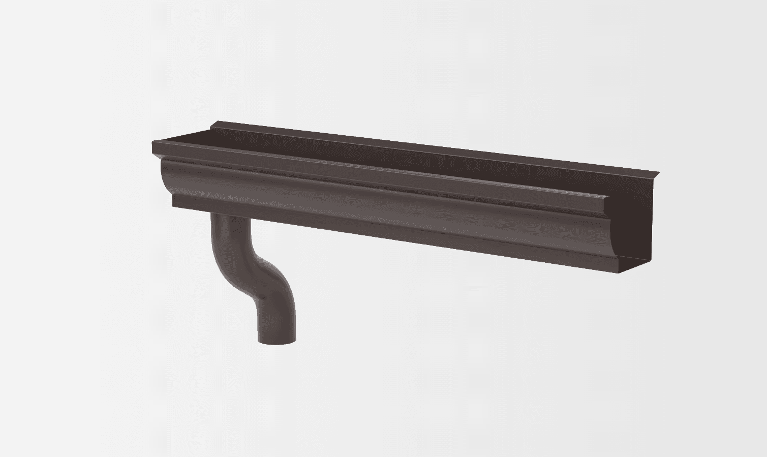
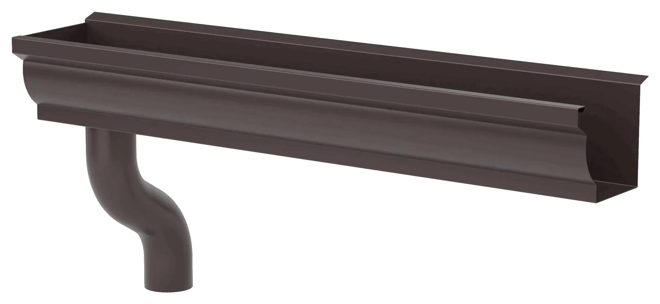
IMS rainwater gutters are made to measure for roof water collection, in classic and design profiles.
- Classic profiles: half-round and square.
- Design profiles: IMS series — IMS-1, IMS-3, IMS-4, IMS-5, IMS-6, IMS-7 and IMS-751 — and QZ series — QZ-101, QZ-102, QZ-103 and QZ-104 — designed for contemporary facades and for industrial unit roofs.
- Materials: polyester-lacquered aluminum, zinc and galvanised steel.
- Standard finishes: RAL 8019, RAL 3009, RAL 9002 and RAL 6002, as well as quartz-zinc, titanium-zinc and galvanised.
- Accessories: external and internal angles, stop ends, downpipes, bends and fixing brackets.
- Manufacture: made to measure in girth and length, in addition to the standard profile range.
- Lead time: 24 hours for standard product and 5 to 10 working days for made-to-measure manufacture.
- Certification: ISO 9001:2015.
This line pairs with ALU-CLICK® wall copings and with VENTUM® chimney and ventilation caps when the project looks for aesthetic consistency across the whole envelope.
Section 13
How to Order a Gutter Without Mistakes
The order comes down to seven pieces of information:
- Girth, or the section required if the calculation hasn't yet been translated into a manufacturing size.
- Length of each straight run, itemised and not added together.
- Number of external and internal angles, counted on the plan.
- Number of stop ends.
- Number, position and diameter of the downpipes.
- Material and finish reference.
- Planned type of support and bracket spacing.
If the calculation hasn't been done yet, with the roof area in horizontal projection and the site location the full sizing can be resolved before defining the order.
Section 14
Common Mistakes on Site
- Not applying the rainfall correction factor. The gutter works all year and fails in the heavy rain event, which is the only one that matters.
- Entering the real area of the slope instead of its horizontal projection, which oversizes the calculation on steep roofs and confuses the result.
- Sizing at 0.5 % and building at 0.5 %, leaving no margin against sag and standing water.
- Reading the table as if it were semicircular when the chosen profile is rectangular, forgetting the 10 % allowance.
- Back-fall from setting out without a line. It creates permanent puddles, dirt deposits and localised corrosion.
- A single downpipe on long gutters. Excessive water paths and no margin against a blockage.
- No expansion joint. Deformation and opening joints by the second or third summer.
- Insufficient roof overhang into the gutter.
- Gutter above the extension of the slope. The overflow happens towards the eaves.
- Brackets too far apart. The gutter sags between supports and in snow areas can pull away.
FAQ
Frequently asked questions
What slope should a gutter have?+
As a working rule, at least 1 %, that is 10 mm per metre, towards the outlet. The tables allow sizing from 0.5 %, but that leaves little margin against sag and standing water. The recommended approach is to start at 1 % and check in the table whether that slope is enough for the served area or whether it's worth going up to 2 %.
Can I install a gutter with no slope?+
It doesn't perform well. A level gutter discharges by depth of water and its real capacity is far below the tabulated one. It also holds water and dirt permanently, which speeds up degradation in any material.
How do I know what rainfall intensity applies to my site?+
BS EN 12056-3 sets the design intensity: 75 mm/hr as the default for most of England, 100 mm/hr in high-exposure areas. For other nations, take the value given for your location. It's the first figure we ask for when someone consults us about sizing, because without it the rest of the calculation doesn't hold up.
How many downpipes do I need?+
It depends on the served area and the diameter chosen. As a spacing criterion, one downpipe every 10 or 12 metres of gutter is reasonable, trying to keep the maximum water path under 5 or 6 metres. Two small downpipes usually perform better than one large one.
Does the table work for square or design-profile gutters?+
Not directly. The table is calculated for a semicircular section. If the section adopted is rectangular, the equivalent section should be 10 % larger than the one obtained as semicircular, and for a specific profile the manufacturer's flow data is the reference.
What happens if the roof receives water from a taller wall?+
That vertical surface also contributes flow and must be considered in the calculation. It's a frequent situation with party walls, courtyards and buildings with blocks of different heights, and it explains quite a few gutters that overflow despite being correctly sized for the slope.
Do these tables work for large industrial roofs?+
They work as a first approximation, but on very large roofs, with internal gutters or with siphonic drainage systems, sizing needs a specific calculation. In those cases it's best resolved with the project designer.
Can a gutter be made to a specific section from the project?+
Yes. We manufacture to measure in girth and length, in addition to the standard profile range, which lets us meet both a calculation requirement and an aesthetic condition of the eaves.
How often should it be checked?+
At least once a year, and preferably before the rainy season. The minimum check is to make sure there are no build-ups in the gutter or at the mouth of the downpipes, that the supports are still firm and that no area of standing water has appeared.
Have a roof to size and don't know where to start?+
Send us the area in horizontal projection and the site location, and we'll propose the complete sizing of the gutter and downpipes.
Share